
Specifications
Design
| Range | TeSys |
|---|---|
| Product or component type | switch body |
| Warranty | 18 months |
Physical
| Mounting support |
|
|---|---|
| [ue] rated operational voltage | 690 V AC 50/60 Hz |
| [ie] rated operational current | 14.5 A AC-23 Ue: 400 V |
| Mechanical durability | 100000 cycles |
| Electrical durability |
|
| Connections - terminals |
|
| Height | 74 mm |
| Width | 55 mm |
| Depth | 60 mm |
| Net weight | 0.2 kg |
| Standards | IEC 60947-3 |
| Product certifications |
|
| Ip degree of protection | IP20 conforming to IEC 60529 |
| Ambient air temperature for operation | -20...50 °C |
| Toxic heavy metal free | Yes |
| Mercury free | Yes |
| Rohs exemption information | Yes |
| Environmental disclosure | ENVPEP2211006EN |
| Reach regulation | Reference contains Substances of Very High Concern above the threshold |
| China rohs regulation | Product out of China RoHS scope |
| Eu rohs directive | Compliant |
Documents & downloads
-
All
-
CAD Files and Packs
-
Technical Data Catalogues
-
Environmental Disclosure
-
Installation Instruction
-
Technical illustration
-
Technical Drawing
-
Certificates (MSDS)
-
Declaration of Conformity
-
Declaration of Conformity (Sustainability)


3 poles VARIO switches disconnector, switch body base 25, 32, 40 A. - Dimensions - Technical drawing
VERSION
1.0
DATE
03 Mar 2022
REVISION
1.0
3 poles VARIO switches disconnector, switch body base 25, 32, 40 A. - Dimensions - Technical drawing
VERSION
1.0
DATE
03 Mar 2022
REVISION
1.0
UL_Certificate_TeSys Vario
VERSION
1.0
DATE
29 Jun 2026
REVISION
1.0
CCC_TeSys Vairo_V02&V01&V0&V1&V2
VERSION
1.0
DATE
25 Nov 2024
REVISION
1.0
DNV-GL Marine Certificate TeSys VARIO - V02-01-0-1-2-3-4-5-6 disconnection switch
VERSION
1.0
DATE
11 Mar 2024
REVISION
1.0
CB_Certificate_TeSys Vario V0&V1&V2&V02
VERSION
1.0
DATE
25 Jul 2023
REVISION
1.0
UKCA Declaration TeSys Mini-Vario, VARIO V02-V01-V0-V1-V2
VERSION
1.0
DATE
21 Jan 2025
REVISION
1.0
EU Declaration TeSys Mini-Vario, VARIO V02-V01-V0-V1-V2
VERSION
1.0
DATE
21 Jan 2025
REVISION
1.0
EU Declaration TeSys Vario_V02C to V2C Switch-disconnector
VERSION
1.0
DATE
14 Nov 2024
REVISION
1.0
UKCA Declaration TeSys Vario V02C to V2C Switch-disconnector
VERSION
1.0
DATE
28 Jun 2023
REVISION
1.0
V0 EU RoHS Directive
VERSION
1.0
DATE
01 Jan 1900
REVISION
1.0
V0 EU RoHS Directive
VERSION
1.0
DATE
01 Jan 1900
REVISION
1.0
V0 EU RoHS Directive
VERSION
1.0
DATE
01 Jan 1900
REVISION
1.0
V0 EU RoHS Directive
VERSION
1.0
DATE
01 Jan 1900
REVISION
1.0
V0 EU RoHS Directive
VERSION
1.0
DATE
01 Jan 1900
REVISION
1.0
V0 EU RoHS Directive
VERSION
1.0
DATE
01 Jan 1900
REVISION
1.0
V0 EU RoHS Directive
VERSION
1.0
DATE
01 Jan 1900
REVISION
1.0
V0 EU RoHS Directive
VERSION
1.0
DATE
01 Jan 1900
REVISION
1.0
V0 REACh Regulation
VERSION
1.0
DATE
01 Jan 1900
REVISION
1.0
V0 REACh Regulation
VERSION
1.0
DATE
01 Jan 1900
REVISION
1.0
V0 REACh Regulation
VERSION
1.0
DATE
01 Jan 1900
REVISION
1.0
V0 REACh Regulation
VERSION
1.0
DATE
01 Jan 1900
REVISION
1.0
Frequently Asked Questions
Which version of Schedule Plus is compatible with C-Gate 3?
Hide ShowSchedule plus V5.4.0 is compatible with C-Gate 3
Release note:

Download link:


How to install and connect an IFE module and TRV00210 units [Video]
Hide ShowInstall IFE module on din mount. Ensure that the back connector lines up with that of the connect on the din rail.
Install TRV00210 units similar to that of the IFE module, ensuring that the connectors are all aligned.
Supply power to the din rail. To verify correct installation, the units’ LEDs will indicate and flash.
The objective of this video is to provide guidance for installing an IFE module with TRV00210 units on a din mount
Can the new Dali gateway 5502DCGP230 firmware be updated?
Hide ShowYes installer can update the firmware of the device in the field
- without disconnecting any connections
- without removing the unit from the switchboard
A USB device port is provided on the front cover of the device as a power source.
Using Space logic C-Bus Commission software >
What is the IP rating for the Iconic Outdoor sockets?
Hide ShowWhat other switch types are compatible to be installed in the Iconic Outdoor switch?
Hide ShowDo the conduit caps come with the Iconic Outdoor?
Hide ShowWhat is the IP rating for the Iconic Outdoor switches?
Hide ShowHow do you remove the cover from Iconic Outdoor once its clipped on?
Hide ShowDo I need to use any caps or silicone on the mounting screws on the Iconic Outdoor?
Hide ShowCan the Iconic Outdoor O3015T Connected Socket be connected to my Wiser Hub?
Hide ShowWhat size conduit entries can be used with Iconic Outdoor?
Hide ShowWhat type of the updates file do the SpaceLogic C-Bus Controllers have?
Hide ShowThe SpaceLogic C-Bus Controllers are 5500NAC2, 5500AC2, 5500NAC, 5500SHAC, LSS5500NAC, LSS5500SHAC.
Updates provide a way to install improvements and new features to the Controller. Updates may require a particular firmware version to be installed.
The Update file has the file extension *.lmup (LMUP)
Note: No updates are available so far
The Updates installation path: Configurator → Utility tab → Install updates
How to upgrade firmware for the SpaceLogic C-Bus Controllers?
Hide ShowThe SpaceLogic C-Bus Controllers are 5500NAC2, 5500AC2, 5500NAC, 5500SHAC, LSS5500NAC, LSS5500SHAC.
Links for Exchange and se.com to download the firmware (image file)
5500NAC2_Firmware_V1.15.0.img
From SE website:
https://www.se.com/au/en/download/document/5500NAC2_Firmware-V1.15.0/
or
https://www.se.com/au/en/product-range/2216-spacelogic-cbus-home-automation-system/?parent-subcategory-id=88010&filter=business-5-residential-and-small-business#software-and-firmware
From SE EcoXpert website:
https://ecoxpert.se.com/spacelogic-c-bus/software-and-firmware/firmware#tab/documents
Upgrade firmware
Access to the Configurator page and System page
The path: Configurator → Utility tab → System button → System tab → Upgrade firmware
Click Choose File button and select the firmware file (5500NAC2_Firmware_V1.15.0.img)
Note:
- Do not switch off the Controller during the installation.
- Clean the browser cache after the installation. Use the settings in your browser or the short cuts [Crtl] + [N] or [Crtl] + [F5].
What are the hardware specifications for a PC to run Schedule Plus V5?
Hide ShowWhat are the hardware specifications for a PC to run Schedule Plus V5?
Schedule Plus V5 PC hardware specifications 08_12_2023
5000SDSPU/5
https://www.clipsal.com/search?q=C-Bus%2C+Schedule+Plus+Ver.+5&datasource=productsC-Bus download tap not displaying in the download website
Hide ShowThe software TAB disappearing is a Browser Cache problem for SE.COM.
 >
>It is a fairly simple fix;
This is how to clear your browser cache only for SE.com, instead of clearing all your cache info for other sites.
Right click> Inspect


Select Application> Storage> tick including third-party cookies then hit > Clear site data
Another option is to run New Incognito window

What shroud would fit the 3025USBC?
Hide ShowDALI broadcasts messaging from the DALI gateway vs DALI broadcasts from a DALI Dual Power Supply via the override Push Buttons
Hide ShowThe differential of the DALI broadcasts messaging from the DALI gateway via a C-Bus Group vs Sending broadcasts from a DALI Dual Power Supply via the Push Buttons on the front of the power supply.
-
Sending broadcasts from the DALI gateway via a C-Bus Group.
-
Sending broadcasts from a DALI Dual Power Supply via the Push Buttons on the front of the power supply.
They're different commands with the same outcome.
Sending broadcast from the DALI gateway via a C-Bus Group use ARC command i.e it come with a fade time before the ARC power level of 254(100%) and 0(Off)

Sending broadcast from a DALI Dual Power Supply via the Push Buttons on the front of the power supply is direct Max and Off
What is the outer dimensions of the CAT5E 2D4P5IPV3B data cable?
Hide ShowSome of the key features are:
- Product standard certification: UL File E 215065
- Application: Horizontal wiring in LAN
- Complaint to RoHS standard: Yes
- Average thickness: 0.18 mm
- Minimum point thickness: 0.15 mm
- Insulation diameter: 0.87 mm
- Rip cord
- Bend radius: 50 mm
Where can I download the Visio and CAD for Dafligateway2 (5502CDGP230)
Hide ShowHow to change the order of the Schedule in PICED so it sits in the correct order that you want on the wiser2 apps
Hide ShowWiser2 apps Widget/Schedule not in order.
To change the order of the widget display in wiser2 apps.
PICED> In widget manager
- Aligning them from low to high by clicking the number column
- Highlight the widget then drag and drop the widget in the order that you please
The order can also be change for scheduler
- Aligning the Schedules from low to high by clicking the number column
- Highlight the schedule widget then drag and drop the widget in the order that you please
Do we have a document for Clipsal Iconic cut-out template?
Hide Show
Yes, see the attached file.
1 to 4 gang switch plate cut-out template
5 and 6 gang switch cut-out templates
Architrave switch cut-out temple
Socket cut-out template
4 gang socket cut-out template
Wiser2 and C-Bus Home Controller (SLHC) both have same part number (5200whc2) but hold a different firmware
Hide ShowBoth wiser have the same part number(5200WHC2) but different Device type
SE.com link to the latest PICED 4.15.2
https://www.se.com/au/en/product-range/2216-spacelogic-cbus-home-automation-system/#software-and-firmware
Old Wiser2
Wiser 2 with WiFi – wiser2firmware_1_33_1.img
Current C-Bus Home Controller (SLHC)
Wiser 2 without WiFi – SLHomeControllerfirmware_2_01_1.img
Firmware update is done via PICED but Alternatively, you can use the option Wiser Manual Update under the Settings from the Web Client and then choose one of the above files for the upgrade.
What device type does the C-BUS Dali2Gateway (5502CDGP230) support?
Hide ShowThe C-BUS Dali2Gateway can currently support DT0, DT1, DT6.

Where to download software for the dali building monitor software package?
Hide Showhttps://download.schneider-electric.com/files?p_Doc_Ref=BuildingMonitor-V6.0.472
Search for DCDALCIP250-2 or DCCABKIT6 in Google

Select document & download and tick software - Release

Click through the pages and look for Building Monitor V6.0.472

How to enable/disable C-Bus power supply for 5516RVF
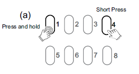
Hide ShowThe integrated C-Bus Power Supply can be enabled or disabled via the front panel by performing a short press on the top right channel button whilst holding down the top left channel button to toggle the enabled state.
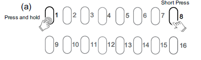
By default, the integrated 200 mA C-Bus Power supply is disabled.
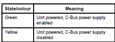
The enabled status of the integrated C-Bus power supply is shown on the Unit indicator.
(Green - Enable, Yellow - Disable).
For 5508RVF and 5504RVF
How to trigger a action selector from C-Bus key switch
Hide ShowHow to trigger a action selector from C-Bus key switch
- SELECT TRIGGER CONTROL FROM SECONDARY APPLICATION (UNIT IDENTIFICATION TAP)
- SELECT THE SECONDARY APPLICATION FROM (P) TO (S) FROM THE SELECT KEY
- SELECT THE TRIGGER CONTROL GROUP AND THEN FUNCTION AS TRIGGER 1 OR 2
- SELECT THE THREE DASH TO SELECT THE ACTION SELECTOR
eg.5085DL

eg.5031nmml

How to install PUSH Module for Dynalite 1.3
Hide ShowPlease see the attached PDF user guide
Also attached is the PEMOD Module file that will be required for the installation via PUSH Project Editor.
How to install PUSH Module for CooLinkNet CoolMasterNet-1.2
Hide ShowPlease see the attached PDF user guide
Also attached is the PEMOD Module file that will be required for the installation via PUSH Project Editor.
How to install PUSH Module for CBus 3.8.2
Hide ShowPlease see the attached PDF user guide
Also attached is the PEMOD Module file that will be required for the installation via PUSH Project Editor.
How to install PUSH Module for Ness D8 2.4
Hide ShowPlease see the attached PDF user guide
Also attached is the PEMOD Module file that will be required for the installation via PUSH Project Editor.
How to install PUSH Module for Camera Script_1.06
Hide ShowPlease see the attached PDF user guide
Also attached is the PEMOD Module file that will be required for the installation via PUSH Project Editor.
How to install PUSH Module for Nero 1.5
Hide ShowPlease see the attached PDF user guide
Also attached is the PEMOD Module file that will be required for the installation via PUSH Project Editor.
How to install PUSH Module for Blustream VideoWall 1.0
Hide ShowPlease see the attached PDF user guide
Also attached is the PEMOD Module file that will be required for the installation via PUSH Project Editor.
How to install PUSH Module for WiserLink 1.1
Hide ShowPlease see the attached PDF user guide
Also attached is the PEMOD Module file that will be required for the installation via PUSH Project Editor.
How to install PUSH Module for Fibaro 1.2
Hide ShowPlease see the attached PDF user guide
Also attached is the PEMOD Module file that will be required for the installation via PUSH Project Editor.
How to install PUSH Module for Somfy RTS v1.3
Hide ShowPlease see the attached PDF user guide
Also attached is the PEMOD Module file that will be required for the installation via PUSH Project Editor.
How to install PUSH Module for Plex 1.2
Hide ShowPlease see the attached PDF user guide
Also attached is the PEMOD Module file that will be required for the installation via PUSH Project Editor.
How to install PUSH Module for Clipsal SILC 1.1
Hide ShowPlease see the attached PDF user guide
Also attached is the PEMOD Module file that will be required for the installation via PUSH Project Editor.
How can WiFi interfere with Wiser and Zigbee?
Hide ShowLuckily, most modern WiFi routers utilize the "Auto Select Channel" function - the router selects the least used channel it can see.
Overview of WiFi and ZigBee channels below:
2.4 GHz WiFi channels
2.4 GHz ZigBee channels
WiFi's three non-overlapping channels (1, 6, and 11) use the exact same frequencies as ZigBee channels 11-22.
We could say that if we select channel 1 of WiFi, the safest one on ZigBee would be 26.
Noting though that Zigbee Channels 25 and 26 are slightly lower powered than the other channels.
Each environment can be different, but generally speaking, wireless communication is affected by obstacles.
Concrete and metal obstacles (armatures, walls, reinforced concrete) are the worst kind of an obstacle.
We can expect that metal and concrete will decrease the range of any wireless device. In such a case, it's possible it will be necessary to install more wired Wiser devices in adjacent rooms to make the network more stable.
How do you distribute MAXBAR from the main row to other rows, keeping the system more professional?
Hide ShowWhat size threaded shaft does the R01 have?
Hide ShowI want to put in two-way switching but can’t run the cables between the mechanisms. Can I achieve wireless two-way switching with Wiser Zigbee?
Hide ShowYou need to create two automations for a 2-way:
- when switch A and switch B are ON, turn switch A and switch B ON
- when switch A and switch B are OFF, turn switch A and switch B OFF
This can be expanded to 3-way, 4-way etc by simply adding the other switches into the respective ON and OFF automations.
Can the Wiser Smoke Alarm integrate into Automations?
Hide ShowCan the Wiser smoke alarm interconnect with my existing alarms?
Hide ShowWhy is the power switch labeled OFF/AUTO on the Wiser Smoke Alarm?
Hide ShowWiser motion sensor – What is detection delay and how do I program it?
Hide ShowBe aware that changing the detection delay value can change the battery life of the product.
To explain how this works we will use 5 minutes detection delay as an example. When motion is detected the sensor sends the signal ‘occupied’ to the hub. If no more motion is detected within the 5 minutes the sensor will send the signal ‘unoccupied’. If there was motion detected during the 5 minutes the 5 minutes will restart again. This will continue restarting until no motion is detected.
To configure the Wiser Motion sensor to control another Wiser product you will need to go into your Automations and create two Automations. One Automation as an ‘on’ and another as an ‘off’.
The ‘on’ Automation can be created by first selecting to add a new Automation. Once open name the Automation accordingly. Add a condition ‘when device status changes’, select the motion sensor, select motion state and occupied. Then add an action of what you want to occur when the motion sensor detects motion. As an example, if you wanted to turn on a device you would add task of ‘run the device’. This will then bring up the list of devices you have to choose from to operate and once you select a device you can then select to turn it on or off.
The ‘off’ Automation is the same as the ‘on’ Automation but select the motion sensor state of ‘unoccupied’ as the condition.
Why is there a QR code on the MAX9 devices?
Hide ShowWhy are Pictograms printed on MAX9 devices?
Hide ShowWhat colours are the new Iconic Outdoor Products available in?
Hide ShowHow can projects created in older versions of Unity Pro be opened and modified by a newer version? How can the project be saved so that it can still be opened with the old version of Unity Pro?
Hide ShowModify program, but do not use function blocks only available in the new libset, or new DTMs. Keep libset version the same as original.
Save project as an archive (.sta).