Standard Series Single Switch Socket Outlet 250V, 10A, Standard Size, Indicator | White Electric
Item Number: 15N-WE
Datasheet

Close
Specifications
Design
| Range of product | Standard Series |
|---|---|
| Product or component type | switched socket |
| Product brand | Clipsal |
| Surface finish | glossy |
Physical
| Control type | ON/OFF button |
|---|---|
| Number of gangs | 1 gang |
| Pin number | 3 |
| Number of power socket outlets | 1 |
| Actuator |
|
| Fixing mode | by screws |
| Local signalling | indicator light |
| Mounting position | horizontal |
| [ue] rated operational voltage | 250 V AC |
| [in] rated current | 10 A |
| Depth | 14 mm |
| Length | 115 mm |
| Width | 73 mm |
| Fixing center | 84 mm |
| Standards |
|
| Environmental disclosure | ENVPEP120506EN |
| China rohs regulation | Product out of China RoHS scope |
| Eu rohs directive | Compliant By Exemption |
Material
| Material | PC (polycarbonate) |
|---|
Documents & downloads
Filter items
-
All
-
Technical Data Catalogues
-
Specification Guide
-
Declaration of Conformity
-
Declaration of Conformity (Sustainability)

Frequently Asked Questions
How do you distribute MAXBAR from the main row to other rows, keeping the system more professional?
Hide Show
MAXBAR with neutral terminal block can be used to distribute active and neutral in the row with main switch. Use the connectors provided with MAXBAR to take active and neutral feed from the row with main switch to take the feed to other rows. You can follow the same process for other rows in switchboard.
What is MAXBAR?
Hide Show
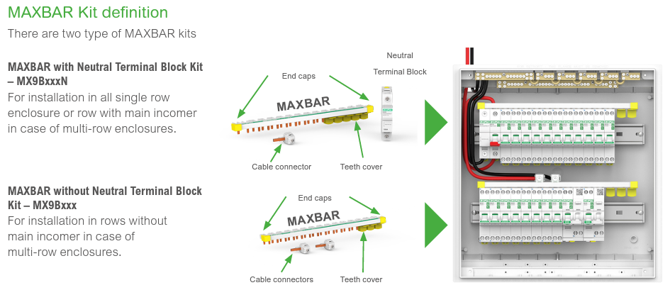
MAXBAR is a top feeding comb busbar able to feed Line & Neutral from the Main incoming Switch or MCB and neutral terminal directly to all type of Clipsal RCBOs and AFDDs.
There are Comb busbar for 1P+N and 3P+N applications. There is one variant with neutral terminal block for rows with Main Switch and another variant for rows without Main switch.
There are Comb busbar for 1P+N and 3P+N applications. There is one variant with neutral terminal block for rows with Main Switch and another variant for rows without Main switch.
How can MAXBAR help me to save time during switchboard installation ?
Hide Show
MAXBAR removes the need for cutting stripping, twisting and managing cables for feeding RCBO & AFDD on typical installation. This helps to achieve installation speed of up to 15x faster with MAXBAR compared to traditional wiring.