Standard Series Cap Number 9 Mounting Screw Cover | Chemical Resistant Orange
Item Number: 9-RO
Datasheet

Specifications
Design
| Range of product | Standard Series |
|---|---|
| Product brand | Clipsal |
Physical
| Mercury free | Yes |
|---|---|
| Rohs exemption information | Yes |
| Environmental disclosure | ENVPEP2103014_V1 |
| Reach regulation | Reference contains Substances of Very High Concern above the threshold |
| China rohs regulation | Product out of China RoHS scope |
| Eu rohs directive | Compliant By Exemption |
Documents & downloads
-
All
-
Technical Data Catalogues
-
End of Life Manual
-
Environmental Disclosure
-
Declaration of Conformity (Sustainability)

9-BK EU RoHS Directive
VERSION
1.0
DATE
01 Jan 1900
REVISION
1.0
9-BK EU RoHS Directive
VERSION
1.0
DATE
01 Jan 1900
REVISION
1.0
9-BK REACh Regulation
VERSION
1.0
DATE
01 Jan 1900
REVISION
1.0
9-BK REACh Regulation
VERSION
1.0
DATE
01 Jan 1900
REVISION
1.0
9-DB EU RoHS Directive
VERSION
1.0
DATE
01 Jan 1900
REVISION
1.0
9-DB EU RoHS Directive
VERSION
1.0
DATE
01 Jan 1900
REVISION
1.0
9-DB REACh Regulation
VERSION
1.0
DATE
01 Jan 1900
REVISION
1.0
9-DB REACh Regulation
VERSION
1.0
DATE
01 Jan 1900
REVISION
1.0
9-EO EU RoHS Directive
VERSION
1.0
DATE
01 Jan 1900
REVISION
1.0
9-EO EU RoHS Directive
VERSION
1.0
DATE
01 Jan 1900
REVISION
1.0
9-EO REACh Regulation
VERSION
1.0
DATE
01 Jan 1900
REVISION
1.0
9-EO REACh Regulation
VERSION
1.0
DATE
01 Jan 1900
REVISION
1.0
9-GY EU RoHS Directive
VERSION
1.0
DATE
01 Jan 1900
REVISION
1.0
9-GY EU RoHS Directive
VERSION
1.0
DATE
01 Jan 1900
REVISION
1.0
9-GY REACh Regulation
VERSION
1.0
DATE
01 Jan 1900
REVISION
1.0
9-GY REACh Regulation
VERSION
1.0
DATE
01 Jan 1900
REVISION
1.0
9-LG EU RoHS Directive
VERSION
1.0
DATE
01 Jan 1900
REVISION
1.0
9-LG EU RoHS Directive
VERSION
1.0
DATE
01 Jan 1900
REVISION
1.0
9-LG REACh Regulation
VERSION
1.0
DATE
01 Jan 1900
REVISION
1.0
9-LG REACh Regulation
VERSION
1.0
DATE
01 Jan 1900
REVISION
1.0
9-RD EU RoHS Directive
VERSION
1.0
DATE
01 Jan 1900
REVISION
1.0
9-RD EU RoHS Directive
VERSION
1.0
DATE
01 Jan 1900
REVISION
1.0
9-RO EU RoHS Directive
VERSION
1.0
DATE
01 Jan 1900
REVISION
1.0
9-RO EU RoHS Directive
VERSION
1.0
DATE
01 Jan 1900
REVISION
1.0
9-RO REACh Regulation
VERSION
1.0
DATE
01 Jan 1900
REVISION
1.0
9-RO REACh Regulation
VERSION
1.0
DATE
01 Jan 1900
REVISION
1.0
9-WE EU RoHS Directive
VERSION
1.0
DATE
01 Jan 1900
REVISION
1.0
9-WE EU RoHS Directive
VERSION
1.0
DATE
01 Jan 1900
REVISION
1.0
9-WE EU RoHS Directive
VERSION
1.0
DATE
01 Jan 1900
REVISION
1.0
9-WE EU RoHS Directive
VERSION
1.0
DATE
01 Jan 1900
REVISION
1.0
Frequently Asked Questions
DNP Mapping Technical Documentation for ION9200
Hide ShowProduct Line: ION 9000 Power meters
Environment: METSEION92030
Resolution:
The DNP3.0 Device Profile Document for the ION9000 meter is not currently available. However, the PM8000 DNP3 Device Profile Guide can be provided as a reference. This guide is expected to closely align with, and in many cases match, the DNP3 profile implemented in the ION9000. The document can be found in this link below.
https://www.se.com/au/en/faqs/FA244205/
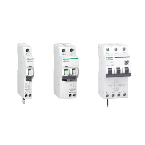
What is the RCD response time and Standard for Acti 9 Range?
Hide ShowThe response times of Acti 9 RCD conform to the specifications of the IEC/EN 61008, IEC/EN 61009 and IEC/EN 62423 (DC leakage current) standards.
Please see the attached document for reference.
What is Thermal Sensor Error (t1CF) on the Altivar Process 900?
Hide ShowIssue:
What is error t1CF on the Altivar Process 900?
Product Line:
Variable Frequency Drives
Environment:
Applies to Altivar Process 900
ATV930
ATV950
ATV960
Cause:
Drive displaying "t1CF" when wiring the sensor to "AI1" and "COM"
Resolution:
t1CF: AI1 thermal sensor Error
Probable Cause:
The thermal sensor monitoring function has detected a thermal sensor error on analog input AI1:
- Open circuit, or
- Short circuit
Remedy: Verify the sensor and its wiring, replace the sensor if needed
This detected error can be cleared with [Auto Fault Reset] Atr or manually with the [Fault Reset Assign] rSF parameter after the cause has disappeared.
t3CF indicates a thermal sensor connected to Analog input 3 triggered the error
t4CF indicates an AI4 thermal sensor error
t5CF indicates an AI5 thermal sensor error detected
If this article does not answer your question, check out our FAQ database that has answers to more commonly asked questions: Frequently Asked Questions - Schneider Electric (se.com)If this FAQ did not solve your issue, you can call us at 1-888-778-2733 Option 2 and then 4 or e-mail us at drive.products.support@se.com to create a case with our Technical Support Team. If you are not located in North America, please contact your local Customer Care Center for assistance: Support | Schneider Electric Global (se.com)
Why can't I send my report from Spark-e-Log via email on my iPhone?
Hide ShowWhy are all my tests in Spark-e-Log coming up as failed?
Hide ShowThe breaking capacity and operating time of the Acti9 iMX+OF shunt trip release module (Ref: A9A26946).
Hide ShowIssue:
What is the breaking capacity and operating time of the Acti9 iMX+OF shunt trip release module (Ref: A9A26946)?
Product Line:
Acti9 iMX+OF Auxiliary Trip Units
Environment:
Used with Acti9 circuit breakers (e.g., iC60, iC65) for remote tripping applications.
Resolution:
Breaking Capacity:
The A9A26946 module does not have its own breaking capacity because it is not a circuit breaker. It operates in conjunction with the associated protection device (e.g., Acti9 iC60/iC65), which determines the system’s breaking capacity.
Operating Time:
• Depends on the control voltage applied.
• For a sudden voltage application (0 → 100% of Un), the iMX operating time can be <10 ms.
• Combined with the associated circuit breaker, the total power circuit breaking time can be approximately <18 ms.
For detailed specifications, refer to Global Module CA908029E.
Can I change the timestamp on my Wiser IP Camera (Indoor and Outdoor)?
Hide ShowWhat is the part number of the insulating shroud to suit Iconic mechanism 40M?
Hide Show90FS-BK is the insulating shroud that suits Iconic mechanism 40M.
For further information, please visit https://www.clipsal.com/Trade/Products/ProductDetail?catno=90FS
How do I conduct a Fault Loop Impedance Test using a 493 Spark-e-Mate installation tester?
Hide ShowPlease view the video.
Do the Wiser Smoke Alarms repeat the Zigbee signal?
Hide ShowToolkit 1.19 fail to load 5753L.PEIRL sensor fix
Hide ShowFix is
Issue resolved by either open in classic by right click or change the preference to classic mode
Toolkit > File> Preferences > then tick classic mode

Do we have an RCD Trip Curve for Acti 9 breakers?
Hide ShowThe maximum break times for these standards are outlined in the document attached with advise on discrimination with RCD devices.
What is the replacement for a Merlin Gerin 26860, RCBO, 240V, 20A, 30mA?
Hide ShowSee link for further details:https://www.se.com/au/en/product/A9D11820/ic60h---earth-leakage-circuit-breaker---1p-%2B-n---c-curve---20-a---30-ma---240-v/
How do you distribute MAXBAR from the main row to other rows, keeping the system more professional?
Hide ShowVIDEO - Spark-e-Mate - How to Change Mode & Disable the Desensitisation Routine
Hide ShowCan the Wiser Smoke Alarm integrate into Automations?
Hide ShowCan the Wiser smoke alarm interconnect with my existing alarms?
Hide ShowWhy is the power switch labeled OFF/AUTO on the Wiser Smoke Alarm?
Hide ShowWhat is MAXBAR?
Hide ShowThere are Comb busbar for 1P+N and 3P+N applications. There is one variant with neutral terminal block for rows with Main Switch and another variant for rows without Main switch.
Wiser motion sensor – What is detection delay and how do I program it?
Hide ShowBe aware that changing the detection delay value can change the battery life of the product.
To explain how this works we will use 5 minutes detection delay as an example. When motion is detected the sensor sends the signal ‘occupied’ to the hub. If no more motion is detected within the 5 minutes the sensor will send the signal ‘unoccupied’. If there was motion detected during the 5 minutes the 5 minutes will restart again. This will continue restarting until no motion is detected.
To configure the Wiser Motion sensor to control another Wiser product you will need to go into your Automations and create two Automations. One Automation as an ‘on’ and another as an ‘off’.
The ‘on’ Automation can be created by first selecting to add a new Automation. Once open name the Automation accordingly. Add a condition ‘when device status changes’, select the motion sensor, select motion state and occupied. Then add an action of what you want to occur when the motion sensor detects motion. As an example, if you wanted to turn on a device you would add task of ‘run the device’. This will then bring up the list of devices you have to choose from to operate and once you select a device you can then select to turn it on or off.
The ‘off’ Automation is the same as the ‘on’ Automation but select the motion sensor state of ‘unoccupied’ as the condition.
How do you perform an RCD test using the 493 Spark-e-Mate installation tester?
Hide ShowPlease view this video.
How to test an RCD to AS/NZS 3003 using a 493 Spark-e-Mate tester?
Hide ShowPlease view the video.
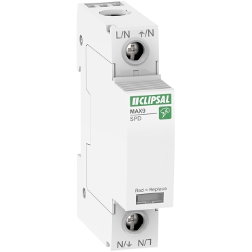
What is the backup protection device for MAX9 SPD?
Hide ShowYou can use 1P 40A MCB (MX9MC140) for 1P SPD (MX9SP140), and 3P 40A MCB (MX9MC340) for 3P SPD
(MX9SP340).
How can MAXBAR help me to save time during switchboard installation ?
Hide ShowWhy is there a QR code on the MAX9 devices?
Hide ShowWhy are Pictograms printed on MAX9 devices?
Hide ShowWhen should I be testing my Wiser Smoke Alarm?
Hide ShowWhen installing the Wiser Smoke Alarm testing of the alarm and interconnection should be done after the product is paired to the Hub and also after any RF pairing is completed.
The Wiser Smoke Alarm is recommended to be tested monthly after installation.
Can you use the 3-position switches with Solis or Solis T range?
Hide ShowIf blind control is required, you can use 2 x 40MBPRL mechanisms using one for UP and one for DOWN
How do I convert Iconic Wiser™ Connected Socket from Zigbee to BLE
Hide ShowSee below video
What is the coil tolerance for Tesys D-line contactors LC1D09 - LC1D38?
Hide ShowLC1D09 - LC1D38 Coil tolerance
Product Line:
Contactors and Starters, IEC
Environment:
Tesys D Contactors
Cause:
Needs the coil tolerance for Tesys D-line contactors LC1D09 - LC1D38.
Resolution:
AC single frequency coils: 50Hz and 60 Hz (-20% / +10%);
AC dual frequency coils: 50Hz (-20% / +10%) ; 60Hz (-15% / +10%)
DC standard coil for LC1D09 -D38 and LC1DT20 to DT40: (-30% / +25%)
DC standard coil for LP1D12 and D25: (-20% / +10%)
DC wide range coil for LP1D12 and D25 : (-30% to +25%)
What is the breakdown of components for 9001KYK117?
Hide ShowBreakdown of components for 9001KYK117
Product Line:
Harmony Push Buttons
Environment:
Harmony Control Stations
Cause:
Product Features
Resolution:
9001KYK117 components are:
1-9001KY1S1 (red enclosure)
1-9001K15 (break glass operator)
1-9001KA1 (1 open and 1 closed contact)
1-9001KN799RP (legend plate)
Replacement glass discs are 9001K57 (package of five)
Where are the wiring diagrams for undervoltage trips (MN) and shunt trips (MX) for the PowerPacT breakers?
Hide ShowCircuit Breakers
Resolution:
There are two terminals on the UVR and the shunt trip accessories to which the control wires are attached (polarity does not matter).
- The shunt trip will trip the circuit breaker if control voltage is applied across the two shunt trip terminals.
- The undervoltage trip will trip the circuit breaker if control voltage is removed from the two undervoltage trip terminals.
PowerPacT H, J, and L document 48940-229-01
PowerPacT M, P, and R document 48049-245-03
What are the dimensions of the 449A mounting block?
Hide ShowSome of the key features are:
- Moulded surface mounting blocks
- With metal inserts
- To suit all standard size accessories
For further information please visit https://www.clipsal.com/products/detail?CatNo=449A&itemno=449A-BK&backto=/search?q&tab-document-1=0

How is an Altivar VFD set to always run a particular speed when no reference input is connected?
Hide ShowWants the Altivar VFD set to always run at a particular speed when no reference input is connected.
Product Line:
Altivar 12, 32, 312, 61, 71, 212, 320
Environment:
All models
Cause:
VFD does not run the motor without a speed reference.
Resolution:
If there is no external speed reference when the VFD gets a run command, then it will always run at the minimum speed programmed to the VFD. Set the minimum speed parameter to the desired run speed. Use parameter LSP for the Altivar12, 32, 312, 320, 61, 71 drives. Use parameter LL for the Altivar 212 drive. These can be adjusted while the motor is running.