Standard Series Automatic Twin Socket Outlet 250VAC, 10A, 1 Pole | White Electric
Item Number: 20-WE
Datasheet

Specifications
Design
Range of product
Product or component type
Product brand
Physical
Quantity per set
Marking
Local signalling
Fixing mode
[in] rated current
[ue] rated operational voltage
Depth
Length
Fixing center
Number of poles
Width
Standards
- AS/NZS 3100
- AS/NZS 3112
- AS/NZS 3133
- AS/NZS 3000:approval number S/1
Environmental disclosure
China rohs regulation
Eu rohs directive
Others
Package 1 bare product quantity
Legacy weee scope
Warranty duration(in months) bmecat
Weee label
Cover type
Unit type of package 1
Number of units in package 1
Package 1 height
Package 1 width
Package 1 length
Package 1 weight
Unit type of package 2
Number of units in package 2
Package 2 height
Package 2 width
Package 2 length
Package 2 weight
Unit type of package 3
Number of units in package 3
Package 3 height
Package 3 width
Package 3 length
Package 3 weight
Sustainable packaging
China rohs label
End of life manual availability
Warranty (in months)
Documents & downloads
-
All
-
Technical Data Catalogues
-
Declaration of Conformity (Sustainability)

Frequently Asked Questions
Do the conduit caps come with the Iconic Outdoor?
Hide ShowWiser2 apps Security Update notice
Hide Show
|
|
Dear SpaceLogic C-Bus Community, We want to notify you about a critical security update for the Wiser 2 app. This update will affect users as the app will no longer support the unsecured Remote Connection feature, which allows connection to the mobile app from outside the home. Users of the Wiser 2 app will receive a push notification about this update in early January 2024, and the new app with the security update will be available for download in February 2024. This update impacts Wiser 1, Wiser 1.5, Wiser MK II, and SpaceLogic C-Bus Home Controller users, with actions varying depending on the controller installed in the system. The push notification that will be sent to Wiser 2 app users in early January, will guide them to a non-indexable web page for details based on the controller they have in their installations. Please refer to the following link for more information: https://www.clipsal.com/wiser-customer-support/wiser-c-bus-security-update We kindly request that you disseminate this information to your customer support teams. Thank you, |
Will the Pro series outlets fit in the Tal Plus skirting duct?
Hide ShowThe power shrouds (PLPSK) are not large enough for the back of the outlet to fit in.
How to change the order of the Schedule in PICED so it sits in the correct order that you want on the wiser2 apps
Hide ShowWiser2 apps Widget/Schedule not in order.
To change the order of the widget display in wiser2 apps.
PICED> In widget manager
- Aligning them from low to high by clicking the number column
- Highlight the widget then drag and drop the widget in the order that you please
The order can also be change for scheduler
- Aligning the Schedules from low to high by clicking the number column
- Highlight the schedule widget then drag and drop the widget in the order that you please
What is the replacement for a Mistral Ceiling Mounted Exhaust Fan to suit hole size approx. 245mm ?
Hide Show| A suitable alternative is CE200 ceiling mounted exhaust fan. It has a cut-out of 240mm Ø. |
The fan comes with a plug and lead for quick and easy installation and the slimline, low-profile and flyproof grille can be easily clipped-off for cleaning.
They are supplied with ball-bearing motor & has a fan diameter of 200mm.
Refer to the attached datasheet for more information.
Do you have a double outlet that has each side wired individually?
Hide ShowC2016/2-WE
16/2MF-WE
15/2V-WE
WSC227/1/2-RG
How to Enable +/- Speeds Around Preset Speeds on ATV320 Drive
Hide ShowIt is possible to set preset speeds on the ATV320 drive and also allow for manual speed adjustments above and below those presets. Please refer to the steps below.
- Set desired preset speeds in [PRESET SPEEDS] menu as shown.
RDY -> CONF -> FULL -> LAC -> Epr (Expert)
RDY-> CONF -> FULL -> Fun [Application Function] -> PSS - [Preset Speeds]
- Set up desired values for speed around reference in [SPEED AROUND REFERENCE] menu.
RDY -> CONF -> FULL -> Fun [Application Function] -> SrE (menu shown below)
Example:
Setting Access level to Expert access.
Assigning Digital Inputs 2 and 3 to control preset speeds (enabling up to three preset speeds)
Preset Speeds 2, 3, and 4 configured to 14 Hz, 18 Hz, and 22 Hz respectively.
Setting Digital input 4 for increase in speed (+).
Setting Digital input 5 for decrease in speed (-).
A +/- speed variation limit of 13% has been applied, restricting any increase or decrease from the preset speed to a maximum of 13%.
Acceleration and deceleration time for changing speed set to 5s.
Wiser2/SLHC Remote Connection for PICED 1.14.2 onward
Hide ShowIn the new Firmware Wiser 2 will only be able to connect remotely using SSL/HTTPS (Port 443 or the External Port that is defined in PICED)
This means HTTP or Port 80 will now longer allow you to login remotely
Whenever you change the remote connection setting, it will force a reboot of the Wiser 2
Wiser 2 with WiFi – wiser2firmware_1_33_1.img, Wiser 2 without WiFi – SLHomeControllerFirmware_2_01_1.img
5200WHC2 Wiser 2 Security Enhancements PICED 1.14.2 onward
Hide ShowNew Password Rules for Wiser 2
- Passwords must be at least 8 characters and not more than 64 characters in length.
- Passwords must contain 1 upper case and 1 lower case.
- Passwords must contain 1 number or 1 special character.
- Passwords must not contain spaces at the beginning or end.
- Passwords must not contain usernames in them.
- Passwords must not be the same as existing passwords.
- Added one more point for mobile and web clients (not applicable for PICED).
SSL Certificates (TLS)
- Uploading Signed Certificate (purchased from DigiCert, GeoTrust, RapidSSL, ZeroSSL)
- Let's Encrypt (Must have a DNS for their domain)
- Self-Sign Certificate
Wiser2 and C-Bus Home Controller (SLHC) both have same part number (5200whc2) but hold a different firmware
Hide ShowBoth wiser have the same part number(5200WHC2) but different Device type
SE.com link to the latest PICED 4.15.2
https://www.se.com/au/en/product-range/2216-spacelogic-cbus-home-automation-system/#software-and-firmware
Old Wiser2
Wiser 2 with WiFi – wiser2firmware_1_33_1.img
Current C-Bus Home Controller (SLHC)
Wiser 2 without WiFi – SLHomeControllerfirmware_2_01_1.img
Firmware update is done via PICED but Alternatively, you can use the option Wiser Manual Update under the Settings from the Web Client and then choose one of the above files for the upgrade.
What Class is Wiser2/SLHC (5200WHC22) Network Support?
Hide ShowUnfortunately, to be able to disable the remote connection for Projector Control Wiser 2 only supports class C network.
A class C network would have a subnet mask of 255.255. 255.0, which means that 24 bits are used for the network. In CIDR notation, this is designated by a /24 following the IP address
Is the Spacelogic Dimmer/Relay 200mA inbuilt Power supply enabled by default?
Hide ShowBy default, the Spacelogic Dimmer/Relay inbuilt 200mA C-Bus Power Supply is disabled. It can be enabled by using the Channel Indicator buttons on the front of the unit.
How to enable/disable C-Bus power supply for 5516RVF
Hide ShowThe integrated C-Bus Power Supply can be enabled or disabled via the front panel by performing a short press on the top right channel button whilst holding down the top left channel button to toggle the enabled state.
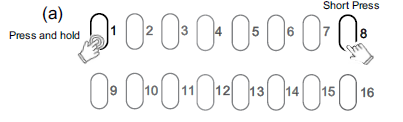
By default, the integrated 200 mA C-Bus Power supply is disabled.
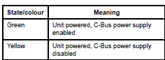
The enabled status of the integrated C-Bus power supply is shown on the Unit indicator.
(Green - Enable, Yellow - Disable).
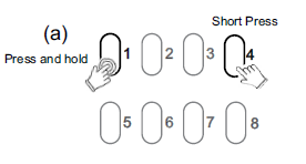
For 5508RVF and 5504RVF
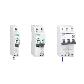
What is the replacement for a Merlin Gerin 26860, RCBO, 240V, 20A, 30mA?
Hide ShowSee link for further details:https://www.se.com/au/en/product/A9D11820/ic60h---earth-leakage-circuit-breaker---1p-%2B-n---c-curve---20-a---30-ma---240-v/
New BMXNOR0200H Web Page Access is Disabled
Hide ShowIssue:
How to Enable BMXNOR0200H Web Access
Product Line:
BMXNOR0200H
Control Expert
Resolution:
By default the Web Access in BMXNOR0200H is disabled due to Cyber Security Requirement and you have to use Control Expert 14. x onwards to Enable the Web Access please follow the below steps ,
Step1: Try to Configure a Dummy application using Control Expert & Enable the Web Access in Security settings and save the application as .STA
Step2: Please Open the .STA file without doing a build & download it to the CPU after which the CPU should have the Web Access
NOTE:
If you want to disable the Web Access then as mentioned in the image these Services can be disabled only on BMXNOR0200H Firmware version V1.7 or higher
How to reset wiser2 back to factory default?
Hide ShowThere are several reasons why you may wish to restart or reset the Wiser 2. If the unit is not communicating properly, a restart (turning power on and off)might be all that is required but for a full factory reset.
NOTE: Performing a Factory "Full" Reset will wipe any programming of the unit and reset the ip addressing to DHCP and the username and password to default - "default"
If a Factory Reset is required follow these steps:
(1) Power OFF the Wiser 2
(2) Press and hold the reset button
(3) While the button is pressed, apply power to Wiser 2
(4) After 25Sec, release the button and allow the Wiser 2 to reboot.

Modicon M200 Battery System Bit
Hide Show- The %S75 System Bit can be used to check the External Battery on the TM200 PLC
What plaster bracket is recommended for the 1044TA, 1044TUA, 1044PA, 1044PUA, 1025XUA & 1025USBC products?
Hide ShowWhat mounting bracket is recommended for the 1044TA, 1044TUA, 1044PA, 1044PUA, 1025XUA & 1025USBC products?
Hide ShowIn New Zealand the flush box recommended for timber frame homes is PDL144M4, which has 120mm mounting centres.
What C-Clip is recommended for the 1044TA, 1044TUA, 1044PA, 1044PUA, 1025XUA & 1025USBC products?
Hide ShowWhat wall box is recommended for the 1044TA, 1044TUA, 1044PA, 1044PUA, 1025XUA & 1025USBC products?
Hide ShowWhat is the replacement AC coil for CAD32 and CAD50 relay?
Hide ShowAC coil replacement for CAD32 and CAD50
Product Line:
Relays
Environment:
Tesys CAD Control Relays
Cause:
Product selection
Resolution:
Volt = coil part number
12 = LXD1J7
21 = LXD1Z7
24 = LXD1B7
32 = LXD1C7
36 = LXD1CC7
42 = LXD1D7
48 = LXD1E7
60 = LXD1EE7
100 = LXD1K7
110 = LXD1F7
115 = LXD1FE7
120 = LXD1G7
127 = LXD1FC7
200 = LXD1L7
208 = LXD1LL7
220/230 = LXD1M7
230 595 21 LXD1P7
230/240 = LXD1U7
277 781 30 LXD1W7
380/400 = LXD1Q7
400 = LXD1V7
415 = LXD1N7
440 = LXD1R7
480 = LXD1T7
600 = LXD1X7
690 = LXD1Y7
How is an Altivar VFD set to always run a particular speed when no reference input is connected?
Hide ShowWants the Altivar VFD set to always run at a particular speed when no reference input is connected.
Product Line:
Altivar 12, 32, 312, 61, 71, 212, 320
Environment:
All models
Cause:
VFD does not run the motor without a speed reference.
Resolution:
If there is no external speed reference when the VFD gets a run command, then it will always run at the minimum speed programmed to the VFD. Set the minimum speed parameter to the desired run speed. Use parameter LSP for the Altivar12, 32, 312, 320, 61, 71 drives. Use parameter LL for the Altivar 212 drive. These can be adjusted while the motor is running.