Datasheet

Specifications
Design
Product brand
Product destination
Product or component type
Physical
Marking
Others
Legacy weee scope
Package 1 bare product quantity
Warranty duration(in months) bmecat
Weee label
Unit type of package 1
Number of units in package 1
Package 1 weight
Sustainable packaging
Warranty (in months)
Documents & downloads
-
All
-
Specification Guide
Frequently Asked Questions
Wiser2 apps Security Update notice
Hide Show
|
|
Dear SpaceLogic C-Bus Community, We want to notify you about a critical security update for the Wiser 2 app. This update will affect users as the app will no longer support the unsecured Remote Connection feature, which allows connection to the mobile app from outside the home. Users of the Wiser 2 app will receive a push notification about this update in early January 2024, and the new app with the security update will be available for download in February 2024. This update impacts Wiser 1, Wiser 1.5, Wiser MK II, and SpaceLogic C-Bus Home Controller users, with actions varying depending on the controller installed in the system. The push notification that will be sent to Wiser 2 app users in early January, will guide them to a non-indexable web page for details based on the controller they have in their installations. Please refer to the following link for more information: https://www.clipsal.com/wiser-customer-support/wiser-c-bus-security-update We kindly request that you disseminate this information to your customer support teams. Thank you, |
DALI broadcasts messaging from the DALI gateway vs DALI broadcasts from a DALI Dual Power Supply via the override Push Buttons
Hide ShowThe differential of the DALI broadcasts messaging from the DALI gateway via a C-Bus Group vs Sending broadcasts from a DALI Dual Power Supply via the Push Buttons on the front of the power supply.
-
Sending broadcasts from the DALI gateway via a C-Bus Group.
-
Sending broadcasts from a DALI Dual Power Supply via the Push Buttons on the front of the power supply.
They're different commands with the same outcome.
Sending broadcast from the DALI gateway via a C-Bus Group use ARC command i.e it come with a fade time before the ARC power level of 254(100%) and 0(Off)

Sending broadcast from a DALI Dual Power Supply via the Push Buttons on the front of the power supply is direct Max and Off
How to change a wrong USB Driver on DCCABKIT6
Hide ShowSuppose the following happens when connecting the DCCABKIT6 cable between Laptop and DALIcontrol Duo Mode 3 Power Supply (DCDALCIP250-2).
In Device Manager find something like

The cable has likely been used with some other product that has recognised the FDTI chip and installed this LibUSB driver which is not recognised by the Simple Wizard which sees a different device ID
BEFORE GOING FURTHER REALISE THAT ONCE COMPLETE THE OTHER DEVICE WILL NO LONGER FIND ITS REQUIRED DRIVER.
Right click on this entry in the Device Manager and select Properties from the menu

And proceed to the Driver tab

…and select <Update Driver>

… and Select <Browse my computer for Drivers>

Select <Let me pick from a list of available drivers on my computer>
With this next Dialog un-tick the Show compatible hardware

In this case you should see Manufacturer FTDI and Select from the Model USB Serial Port which should start the install finishing with…

From here you should now be able to connect.
It is important to note that when connecting to the DALIcontrol Duo Mode 3 Power Supply (DCDALCIP250-2) with the DCCABKIT6 programming cable and running DCBMWizard or SimpleWizard that the power supply be in mode 1. To achieve this on the DCDALCIP250-2 press and hold the <ON A> button and momentarily press the <TEST A> button. The Line A indicator will single pulse 5x to indicate the mode.
If there is a compatible driver installed you can try tick Show Compatible hardware, then try selecting one of the drivers below.

If there are no drivers to be found on the Computer in question it is then possible to download the software by going to the following on your web browser https://support.arduino.cc/hc/en-us/articles/4411305694610-Install-or-update-FTDI-drivers and follow the instructions laid out.
Also go to https://ftdichip.com/drivers/ and follow up with https://ftdichip.com/document/installation-guides/
How to confirm if the C-Bus Automation 5500AC2/NAC2 is connected to the internet
Hide ShowUnder Configurator > System > Status > Network Utility

Type google.com in to the IP/Hostname field

If successful you will see package transmit and receive
Which version of Schedule Plus is compatible with C-Gate 3?
Hide ShowSchedule plus V5.4.0 is compatible with C-Gate 3
Release note:

Download link:


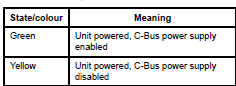
How to enable/disable C-Bus power supply for 5516RVF
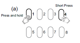
Hide ShowThe integrated C-Bus Power Supply can be enabled or disabled via the front panel by performing a short press on the top right channel button whilst holding down the top left channel button to toggle the enabled state.
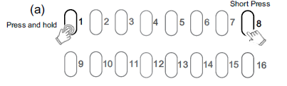
By default, the integrated 200 mA C-Bus Power supply is disabled.
The enabled status of the integrated C-Bus power supply is shown on the Unit indicator.
(Green - Enable, Yellow - Disable).
For 5508RVF and 5504RVF
How do we use C Bus in Prestige series plates?
Hide ShowIs it a bell press mech and a bus coupler or can you use a 30 series C Bus Master and Slave mech with the bell press mech front end?
The 30 mech adapter provides a led indicator.
The bus coupler plus momentary Prestige button looks better but you lose the led indicator

How to Factory Reset daligateway2 (5502CDGP230) to original manufacturer settings
Hide ShowTo factory reset the daligateway2. Simply press the SR button with pointy device i.e a paper clip for 10 Seconds. Release then a long press for more than 0.5 sec.


Blue Open Studio Alarm history are not retaining after 24 hours
Hide ShowIssue:
BLUE Open Studio is not retaining ALARMs History after 24 Hours .
Product Line:
Blue Open Studio .
Resolution:
The Alarm Object Properties Filters -> Interval is set to Period by default,
Changing the Interval settings to Latest or specify a Period should solve the issue.
How do I connect a hybrid inverter to MAXBAR+?
Hide ShowWhere there is a hybrid inverter with DC coupled battery, connect AC circuit to solar position on the MAXBAR+.
In this instance, the battery position on MAXBAR+ can be used for the second solar system or sub board.
Please ensure to affix the appropriate sticker, provided in the New Energy Protection Kit, to MAXBAR+ and the enclosure.
Can the battery & solar MCB's from the New Energy Protection kits be replaced for different current ratings?
Hide ShowYes, solar & battery MCB's can be replaced for higher or lower current ratings as long the combined potential current from solar and battery does not exceed 100A.
What are the most suitable enclosures for MAXBAR+?
Hide ShowThe most suitable enclosure for MAXBAR+ busbars are Clipsal MAX9 Type 3 plastic enclosures due to 150mm spacing between din rails.
For comprehensive list of suitable Clipsal enclosures, refer to MAXBAR+ Complementary Technical Guide.
What makes MAXBAR+ different to other busbars?
Hide ShowMAXBAR+ is specifically designed to help protect switchboards against overloading from multiple energy sources including grid, solar, battery & in the future EV to grid.
MAXBAR+ groups all energy sources on to one busbar then distributes outgoing energy via the dedicated home circuit.
MAXBAR+ comes with predefined positions for circuit protection devices to ensure that current flowing on the busbar does not accumulate from multiple energy sources & therefore protect against overloading.
Can the EV charging RCBO be replaced with a different current rating?
Hide ShowYes, the EV charging RCBO can be replaced with lower current rating if required.
Clipsal recommends 40A circuits with appropriately sized cable to avoid any potential nuisance tripping.
Can circuit protection devices in New Energy Protection Kits be repositioned on MAXBAR+?
Hide ShowMAXBAR+ comes with predefined positions for circuit protection devices to ensure that current flowing on the busbar does not accumulate from multiple energy sources & therefore protect against overloading, aided by pictograms
MAXBAR+ is intended to future-proof switch boards for new energy sources like solar, battery & EV to grid.
Is MAXBAR+ cuttable?
Hide ShowNo, MAXBAR+ is specifically designed not to be cut.
MAXBAR+ is intended to future-proof switch boards for new energy sources like solar, battery & EV to grid.
Where space in existing switch boards is limited, Clipsal recommends the use of an appropriate sub board.
Can you bottom feed MAXBAR+?
Hide ShowNo, MAXBAR+ is designed to be fitted to top side of Clipsal MAX9 circuit protection devices.
How do I connect two solar invertors to MAXBAR+?
Hide ShowWhere there are two solar inverters, connect the second inverter to the battery position on the MAXBAR+.
Please ensure to affix spare solar sticker, provided in the New Energy Protection Kit, to MAXBAR+ and the enclosure.
Is Clipsal MAXBAR+ compatible with all battery backup systems?
Hide ShowIssue:
I am adding MAXBAR+ to a house with existing battery backup system
Resolution:
MAXBAR+ is compatible with most battery systems currently on the market, however some systems use a separate backup interface/gateway which may have built in metering.
Using MAXBAR+ in these instances could cause issues with the battery systems app as the metering could be bypassed.
Is it possible to connect a second sub board to MAXBAR+?
Hide ShowIssue:
I am adding MAXBAR+ to a house with 2 sub boards
Resolution:
Where there is just one inverter, then a second sub board can be connected to battery position on MAXBAR+.
Please ensure to affix spare sub board sticker to MAXBAR+ & enclosure provided in New Energy Protection Kit.
Are the teeth covers the same for MAXBAR & ResiMAX busbar?
Hide ShowIssue:
Instead of throwing out teeth covers, can they be reused on other busbars
Resolution:
Yes, they are the same MAXBAR & ResiMAX busbars - RMXPT120 (set of 20).