Clipsal - Max 4 Mini Neutral link 100 A 500 V 6 hole with cover front wiring Black
Item Number: L6
Datasheet

Specifications
Design
| Range | MAX9 |
|---|---|
| Product brand | Clipsal |
| Range of product | Blue Point |
| Product or component type | neutral link |
Physical
| [in] rated current | 100 A |
|---|---|
| [ue] rated operational voltage | 500 V |
| Connector type | screw terminals |
| Number of poles | 1 |
| Mercury free | Yes |
| Rohs exemption information | Yes |
| Environmental disclosure | ENVPEP2206007EN |
| Reach regulation | Reference contains Substances of Very High Concern above the threshold |
| China rohs regulation | Product out of China RoHS scope |
| Eu rohs directive | Compliant By Exemption |
| California proposition 65 | WARNING: This product can expose you to chemicals including: Lead, which is known to the State of California to cause cancer and birth defects or other reproductive harm. For more information go to www.P65Warnings.ca.gov |
Documents & downloads
-
All
-
Technical Data Catalogues
-
Specification Guide
-
Declaration of Conformity (Sustainability)

Frequently Asked Questions
How to change a wrong USB Driver on DCCABKIT6
Hide ShowSuppose the following happens when connecting the DCCABKIT6 cable between Laptop and DALIcontrol Duo Mode 3 Power Supply (DCDALCIP250-2).
In Device Manager find something like

The cable has likely been used with some other product that has recognised the FDTI chip and installed this LibUSB driver which is not recognised by the Simple Wizard which sees a different device ID
BEFORE GOING FURTHER REALISE THAT ONCE COMPLETE THE OTHER DEVICE WILL NO LONGER FIND ITS REQUIRED DRIVER.
Right click on this entry in the Device Manager and select Properties from the menu

And proceed to the Driver tab

…and select <Update Driver>

… and Select <Browse my computer for Drivers>

Select <Let me pick from a list of available drivers on my computer>
With this next Dialog un-tick the Show compatible hardware

In this case you should see Manufacturer FTDI and Select from the Model USB Serial Port which should start the install finishing with…

From here you should now be able to connect.
It is important to note that when connecting to the DALIcontrol Duo Mode 3 Power Supply (DCDALCIP250-2) with the DCCABKIT6 programming cable and running DCBMWizard or SimpleWizard that the power supply be in mode 1. To achieve this on the DCDALCIP250-2 press and hold the <ON A> button and momentarily press the <TEST A> button. The Line A indicator will single pulse 5x to indicate the mode.
If there is a compatible driver installed you can try tick Show Compatible hardware, then try selecting one of the drivers below.

If there are no drivers to be found on the Computer in question it is then possible to download the software by going to the following on your web browser https://support.arduino.cc/hc/en-us/articles/4411305694610-Install-or-update-FTDI-drivers and follow the instructions laid out.
Also go to https://ftdichip.com/drivers/ and follow up with https://ftdichip.com/document/installation-guides/
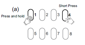
How to enable/disable C-Bus power supply for 5516RVF
Hide ShowThe integrated C-Bus Power Supply can be enabled or disabled via the front panel by performing a short press on the top right channel button whilst holding down the top left channel button to toggle the enabled state.
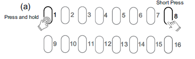
By default, the integrated 200 mA C-Bus Power supply is disabled.
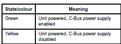
The enabled status of the integrated C-Bus power supply is shown on the Unit indicator.
(Green - Enable, Yellow - Disable).
For 5508RVF and 5504RVF
How do we use C Bus in Prestige series plates?
Hide ShowIs it a bell press mech and a bus coupler or can you use a 30 series C Bus Master and Slave mech with the bell press mech front end?
The 30 mech adapter provides a led indicator.
The bus coupler plus momentary Prestige button looks better but you lose the led indicator

How do I connect a hybrid inverter to MAXBAR+?
Hide ShowWhere there is a hybrid inverter with DC coupled battery, connect AC circuit to solar position on the MAXBAR+.
In this instance, the battery position on MAXBAR+ can be used for the second solar system or sub board.
Please ensure to affix the appropriate sticker, provided in the New Energy Protection Kit, to MAXBAR+ and the enclosure.
C-Bus Cable for underground
Hide ShowTypically for C-Bus underground cable use it needs to be a Cat5E UTP cable with the similar characteristics / impedance as the C-Bus 5005C305B cable.
If you use an underground CAT5E data cable from brands such as belden or garland etc
We would recommend you ask the supplier to provide confirmation they can provide a CAT5E UTP underground equivalent cable Gel filled.
Do not use shielded cabling.

