Standard Series Single Switch Socket Outlet 250V,10A, Skirt Mount | White Electric
Item Number: 16-WE
Datasheet

Specifications
Design
Range of product
Product or component type
Product brand
Surface finish
Physical
Control type
Number of gangs
Pin number
Number of power socket outlets
Actuator
- switch
- rocker
Fixing mode
Local signalling
Mounting position
[ue] rated operational voltage
[in] rated current
Depth
Length
Width
Fixing center
Standards
- AS/NZS 3100
- AS/NZS 3112
- AS/NZS 3133:approval number S/1
Mercury free
Rohs exemption information
Environmental disclosure
Eu rohs directive
Reach regulation
Reach regulation
China rohs regulation
Eu rohs directive
China rohs regulation
Material
Material
Others
Legacy weee scope
Package 1 bare product quantity
Package 2 bare product quantity
Average percentage of recycled plastic content
Warranty duration(in months) bmecat
Weee label
Weee applicability
Unit type of package 1
Number of units in package 1
Package 1 height
Package 1 width
Package 1 length
Package 1 weight
Unit type of package 2
Number of units in package 2
Package 2 height
Package 2 width
Package 2 length
Package 2 weight
Sustainable packaging
Pvc free
Halogen-free status
Take-back
Product contributes to saved and avoided emissions
Removable battery
Average percentage of recycled metal content
Packaging made with recycled cardboard
Packaging without single use plastic
China rohs label
Halogen-free status
Pvc free
End of life manual availability
Take-back
Warranty (in months)
Documents & downloads
-
All
-
Technical Data Catalogues
-
Specification Guide
-
Declaration of Conformity (Sustainability)

16-BK EU RoHS Declaration
VERSION
1.0
DATE
01 Jan 1900
REVISION
1.0
16-BK EU RoHS Declaration
VERSION
1.0
DATE
01 Jan 1900
REVISION
1.0
16-CM EU RoHS Declaration
VERSION
1.0
DATE
01 Jan 1900
REVISION
1.0
16-CM EU RoHS Declaration
VERSION
1.0
DATE
01 Jan 1900
REVISION
1.0
16-RD EU RoHS Declaration
VERSION
1.0
DATE
01 Jan 1900
REVISION
1.0
16-RD EU RoHS Declaration
VERSION
1.0
DATE
01 Jan 1900
REVISION
1.0
Frequently Asked Questions
Control Expert V16.2 System Requirements
Hide ShowDo you have a double outlet that has each side wired individually?
Hide ShowC2016/2-WE
16/2MF-WE
15/2V-WE
WSC227/1/2-RG
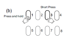
How to enable/disable the C-Bus system clock generator for 5516RVF
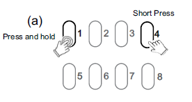
Hide ShowThe integrated C-Bus Clock generator can be enabled or disabled via the front panel by performing a short press on the top second-to-right button whilst holding down the top left channel button to toggle the enabled state.
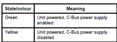
The enabled status of the integrated C-Bus Clock is shown on the C-Bus indicator.
(Green - Enable, Yellow - Disable).
For 5508RVF and 5504RVF
Is the Spacelogic Dimmer/Relay 200mA inbuilt Power supply enabled by default?
Hide ShowBy default, the Spacelogic Dimmer/Relay inbuilt 200mA C-Bus Power Supply is disabled. It can be enabled by using the Channel Indicator buttons on the front of the unit.
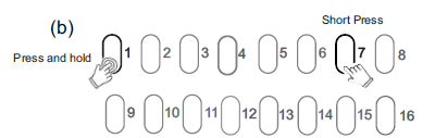
How to enable/disable C-Bus power supply for 5516RVF
Hide ShowThe integrated C-Bus Power Supply can be enabled or disabled via the front panel by performing a short press on the top right channel button whilst holding down the top left channel button to toggle the enabled state.
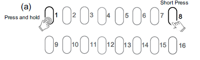
By default, the integrated 200 mA C-Bus Power supply is disabled.
The enabled status of the integrated C-Bus power supply is shown on the Unit indicator.
(Green - Enable, Yellow - Disable).
For 5508RVF and 5504RVF
What does the 16AX mean on the PDL 681MT16WH
Hide ShowWhat is the replacement AC coil for CAD32 and CAD50 relay?
Hide ShowAC coil replacement for CAD32 and CAD50
Product Line:
Relays
Environment:
Tesys CAD Control Relays
Cause:
Product selection
Resolution:
Volt = coil part number
12 = LXD1J7
21 = LXD1Z7
24 = LXD1B7
32 = LXD1C7
36 = LXD1CC7
42 = LXD1D7
48 = LXD1E7
60 = LXD1EE7
100 = LXD1K7
110 = LXD1F7
115 = LXD1FE7
120 = LXD1G7
127 = LXD1FC7
200 = LXD1L7
208 = LXD1LL7
220/230 = LXD1M7
230 595 21 LXD1P7
230/240 = LXD1U7
277 781 30 LXD1W7
380/400 = LXD1Q7
400 = LXD1V7
415 = LXD1N7
440 = LXD1R7
480 = LXD1T7
600 = LXD1X7
690 = LXD1Y7