

Specifications
Design
| Range | TeSys |
|---|---|
| Product or component type | switch body |
Physical
| Mounting support |
|
|---|---|
| [ue] rated operational voltage | 690 V AC 50/60 Hz |
| [ie] rated operational current | 41.5 A AC-23 Ue: 400 V |
| Mechanical durability | 30000 cycles |
| Electrical durability |
|
| Connections - terminals |
|
| Height | 83 mm |
| Width | 60 mm |
| Depth | 65 mm |
| Net weight | 0.5 kg |
| Standards | IEC 60947-3 |
| Product certifications |
|
| Ip degree of protection | IP20 conforming to IEC 60529 |
| Ambient air temperature for operation | -20...50 °C |
| Toxic heavy metal free | Yes |
| Mercury free | Yes |
| Rohs exemption information | Yes |
| Environmental disclosure | ENVPEP2211006EN |
| Eu rohs directive | Compliant |
Documents & downloads
-
All
-
CAD Files and Packs
-
Technical Data Catalogues
-
Environmental Disclosure
-
Installation Instruction
-
Technical illustration
-
Technical Drawing
-
Certificates (MSDS)
-
Declaration of Conformity
-
Declaration of Conformity (Sustainability)


3 poles VARIO switches disconnector, switch body base 63, 80 A. - Dimensions - Technical drawing
VERSION
1.0
DATE
03 Mar 2022
REVISION
1.0
3 poles VARIO switches disconnector, switch body base 63, 80 A. - Dimensions - Technical drawing
VERSION
1.0
DATE
03 Mar 2022
REVISION
1.0
UL_Certificate_TeSys Vario
VERSION
1.0
DATE
29 June 2026
REVISION
1.0
CCC_TeSys Vario_V3&V4
VERSION
1.0
DATE
25 Nov 2024
REVISION
1.0
DNV-GL Marine Certificate TeSys VARIO - V02-01-0-1-2-3-4-5-6 disconnection switch
VERSION
1.0
DATE
11 Mar 2024
REVISION
1.0
CB_Certificate_TeSys V3&V4
VERSION
1.0
DATE
23 Aug 2023
REVISION
1.0
CSA Certificate_ TeSys Vario
VERSION
1.0
DATE
30 Dec 2022
REVISION
1.0
V3 EU RoHS Directive
VERSION
1.0
DATE
01 Jan 1900
REVISION
1.0
V3 EU RoHS Directive
VERSION
1.0
DATE
01 Jan 1900
REVISION
1.0
V3 EU RoHS Directive
VERSION
1.0
DATE
01 Jan 1900
REVISION
1.0
V3 EU RoHS Directive
VERSION
1.0
DATE
01 Jan 1900
REVISION
1.0
V3 EU RoHS Directive
VERSION
1.0
DATE
01 Jan 1900
REVISION
1.0
V3 EU RoHS Directive
VERSION
1.0
DATE
01 Jan 1900
REVISION
1.0
V3 EU RoHS Directive
VERSION
1.0
DATE
01 Jan 1900
REVISION
1.0
V3 EU RoHS Directive
VERSION
1.0
DATE
01 Jan 1900
REVISION
1.0
V3 POP Directive
VERSION
1.0
DATE
01 Jan 1900
REVISION
1.0
V3 POP Directive
VERSION
1.0
DATE
01 Jan 1900
REVISION
1.0
V3 POP Directive
VERSION
1.0
DATE
01 Jan 1900
REVISION
1.0
V3 POP Directive
VERSION
1.0
DATE
01 Jan 1900
REVISION
1.0
V3 POP Directive
VERSION
1.0
DATE
01 Jan 1900
REVISION
1.0
V3 POP Directive
VERSION
1.0
DATE
01 Jan 1900
REVISION
1.0
V3 POP Directive
VERSION
1.0
DATE
01 Jan 1900
REVISION
1.0
V3 POP Directive
VERSION
1.0
DATE
01 Jan 1900
REVISION
1.0
V3 REACh Regulation
VERSION
1.0
DATE
01 Jan 1900
REVISION
1.0
V3 REACh Regulation
VERSION
1.0
DATE
01 Jan 1900
REVISION
1.0
V3 REACh Regulation
VERSION
1.0
DATE
01 Jan 1900
REVISION
1.0
V3 REACh Regulation
VERSION
1.0
DATE
01 Jan 1900
REVISION
1.0
V3 REACh Regulation
VERSION
1.0
DATE
01 Jan 1900
REVISION
1.0
V3 REACh Regulation
VERSION
1.0
DATE
01 Jan 1900
REVISION
1.0
V3 REACh Regulation
VERSION
1.0
DATE
01 Jan 1900
REVISION
1.0
V3 REACh Regulation
VERSION
1.0
DATE
01 Jan 1900
REVISION
1.0
Frequently Asked Questions
VAMPSET tool error: "This VAMP device requires VAMPSET version 2.2.210 or higher for configuration. I cannot find this version on the website. How can I obtain it?"
Hide ShowIssue:
VAMPSET tool error:"This VAMP device requires VAMPSET version 2.2.210 or higher for configuration. I cannot find this version on the website. How can I obtain it?"
Product Line:
V321 Protection Relay, Easergy Pro Tool , VAMPSET Tool
Environment:
VAMP321 relay configuration and communication software
Resolution:
The message is expected behavior for certain VAMP321 firmware versions. Although the relay requests VAMPSET version 2.2.210 or higher, this software version is generally no longer available for public download.
The VAMP321 is part of the VAMP protection relay family, which historically used VAMPSET as the engineering and configuration software. Most VAMP relay models have since reached the end of their production lifecycle, while the VAMP321 continues to be maintained and supported.
As part of the product evolution, Schneider Electric migrated VAMP321 configuration support from VAMPSET to Easergy Pro. Software compatibility depends on the relay firmware version:
- Older VAMP321 firmware versions are configured using VAMPSET.
- Firmware version 20.116 and later should be configured using Easergy Pro.
Based on testing performed with VAMP321 devices, it is normal to encounter situations where:
- An older VAMP321 communicates only through VAMPSET.
- A newer VAMP321 requires Easergy Pro for communication and configuration.
Therefore, if your VAMP321 is running firmware 20.116 or later, Schneider Electric recommends using Easergy Pro instead of searching for VAMPSET 2.2.210.
Additionally, it is recommended to use the latest available version of Easergy Pro, as earlier releases had known communication issues with some VAMP321 devices that were resolved in later versions.
Latest Easergy Pro downloads are available at:
https://www.se.com/au/en/product-range/63736-esetup-easergy-pro/#software-and-firmware
If the relay is running an older firmware version that genuinely requires VAMPSET, and the required VAMPSET version cannot be found on the public website, contact Schneider Electric Technical Support for assistance in identifying the correct engineering tool and software package.
Modicon M258 stuck in a boot loop after a firmware update?
Hide ShowQuestion:
A Modicon M258 controller powers up, all LEDs turn on briefly, RUN/MS flashes or turns off, and the Ethernet LEDs continue flashing red/green in a repeating 3-flash cycle. What can cause this boot loop and how can it be recovered?
Answer:
This behaviour could occur if the firmware loaded into the Modicon M258 is not compatible with the controller hardware version.
For M258 PV16 / hardware version 4 controllers, the required firmware depends on the SoMachine version being used:
- SoMachine V3.x: firmware V2.0.31.40
- SoMachine V4.x: firmware V4.0.3.6
Using an incompatible firmware version can cause the controller to reboot continuously and fail to complete startup.
The recommended recovery method is to reload the correct firmware using a USB memory key. Firmware update by USB key is preferred because older versions of Controller Assistant may not check the M258/LMC058 hardware version before downloading firmware. This can allow an incompatible firmware version to be loaded.
After the correct firmware has been reloaded:
1. Reconnect to the controller using the appropriate SoMachine version.
2. Download the correct application.
3. Update the boot application.
4. Power cycle the controller and confirm that the controller starts normally.
If the controller remains in a boot loop after reloading the correct firmware by USB key, and the correct firmware version for the hardware has been confirmed, no further recovery action may be available. In this condition, the controller may be permanently damaged and require replacement.
References:
- For USB firmware reload procedure, refer to Schneider Electric FAQ FA339601.
- For setting the M258/LMC058 to start in RUN mode and updating the boot application, refer to Schneider Electric FAQ FA243994.
Install and activate SoMachine V3.1 to avoid Demo mode?
Hide ShowQuestion:
When installing SoMachine V3.1, the software installs in Demo mode or displays an error saying the Part Number / Serial Number is wrong or incomplete. What are the correct installation and activation steps?
Answer:
SoMachine V3.1 may install in Demo mode if the installation is completed without entering a valid Part Number and Serial Number, or if the entered Part Number / Serial Number is incorrect.
To correctly install and activate SoMachine V3.1, follow the steps below:
1. Fully uninstall any existing SoMachine V3.1 installation from the PC.
2. Restart the PC after the uninstall is complete.
3. Start the SoMachine V3.1 installation again.
4. When prompted during installation, enter the correct Part Number and Serial Number.
5. Complete the installation.
6. Open the Schneider Electric License Manager.
7. Generate or note the Code Entry Number and Computer ID from the License Manager.
8. Go to the Schneider Electric software registration page:
https://www.se.com/ww/en/work/support/software-registration/
9. Enter the required details to generate the Authorization Code. Use by web:
10. Get the Code and Computer ID
11. Return to the License Manager and enter the Authorization Code.
12. Confirm that SoMachine V3.1 is activated and no longer running in Demo mode.
If SoMachine V3.1 was already installed without a valid Part Number and Serial Number, the software may remain in Demo mode. In this situation, the recommended action is to fully uninstall SoMachine V3.1 and reinstall it using the correct license details during the installation process.
Notes:
- SoMachine V3.1 is a legacy software version and is no longer commercialized.
- The installation media may still install correctly, but activation requires valid license information.
- If an incorrect Part Number or Serial Number is entered, the installation may proceed as a Demo installation.
- For future projects, migration to EcoStruxure Machine Expert should be considered where possible.
How can I update the firmware of an eDLT to v2.X?
Hide ShowA firmware upgrade of an eDLT to v2.X can only be done in C-Bus Commission; however, the eDLT must support hardware v3.0.
Some key points to remember when performing a firmware upgrade using C-Bus Commission:
• In C-Bus Toolkit, you can only upgrade an eDLT’s firmware up to v1.8
• Once you upgrade the firmware to v2.X, you cannot revert to an earlier version
• A firmware upgrade to v2.X will factory reset the unit; the device will need to be re-programmed
Can I program the properties of an eDLT using C-Bus Commission?
Hide ShowSpaceLogic C-Bus Commission v2.15.0 or higher supports the capability to program eDLT's with the following characteristic:
Hardware: v3.0
Firmware: v2.X
What do the terms PWH1 I1 and PWH1 V1 mean in the Power Harmonics module?
Hide ShowProduct Line: ION 9000 Power meters
Environment: METSEION92030
Resolution:
Explanation of Power Harmonics Angle Parameters
The parameters PWH1 V1/V2/V3 Angle and PWH1 I1/I2/I3 Angle are sourced from the Power Harmonics module under the Fundamental Power group. These parameters represent the phase angles, measured in degrees, of voltage and current for each phase at the fundamental frequency.
- PWH1 V1 Angle → Phase angle of Voltage Phase A
- PWH1 V2 Angle → Phase angle of Voltage Phase B
- PWH1 V3 Angle → Phase angle of Voltage Phase C
- PWH1 I1 Angle → Phase angle of Current Phase A
- PWH1 I2 Angle → Phase angle of Current Phase B
- PWH1 I3 Angle → Phase angle of Current Phase C
These values are commonly used for power quality analysis and phase relationship verification at the fundamental frequency.
C-Bus download tap not displaying in the download website
Hide ShowThe software TAB disappearing is a Browser Cache problem for SE.COM.
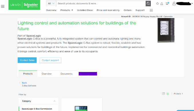 >
>It is a fairly simple fix;
This is how to clear your browser cache only for SE.com, instead of clearing all your cache info for other sites.
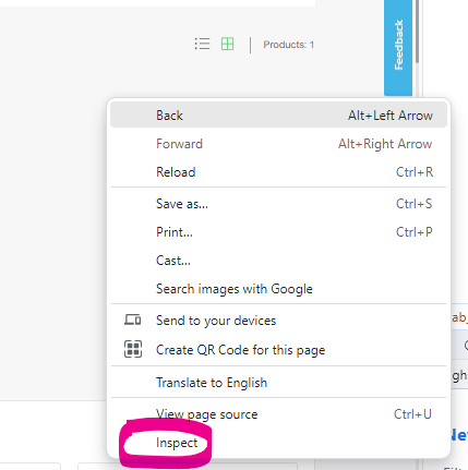
Right click> Inspect
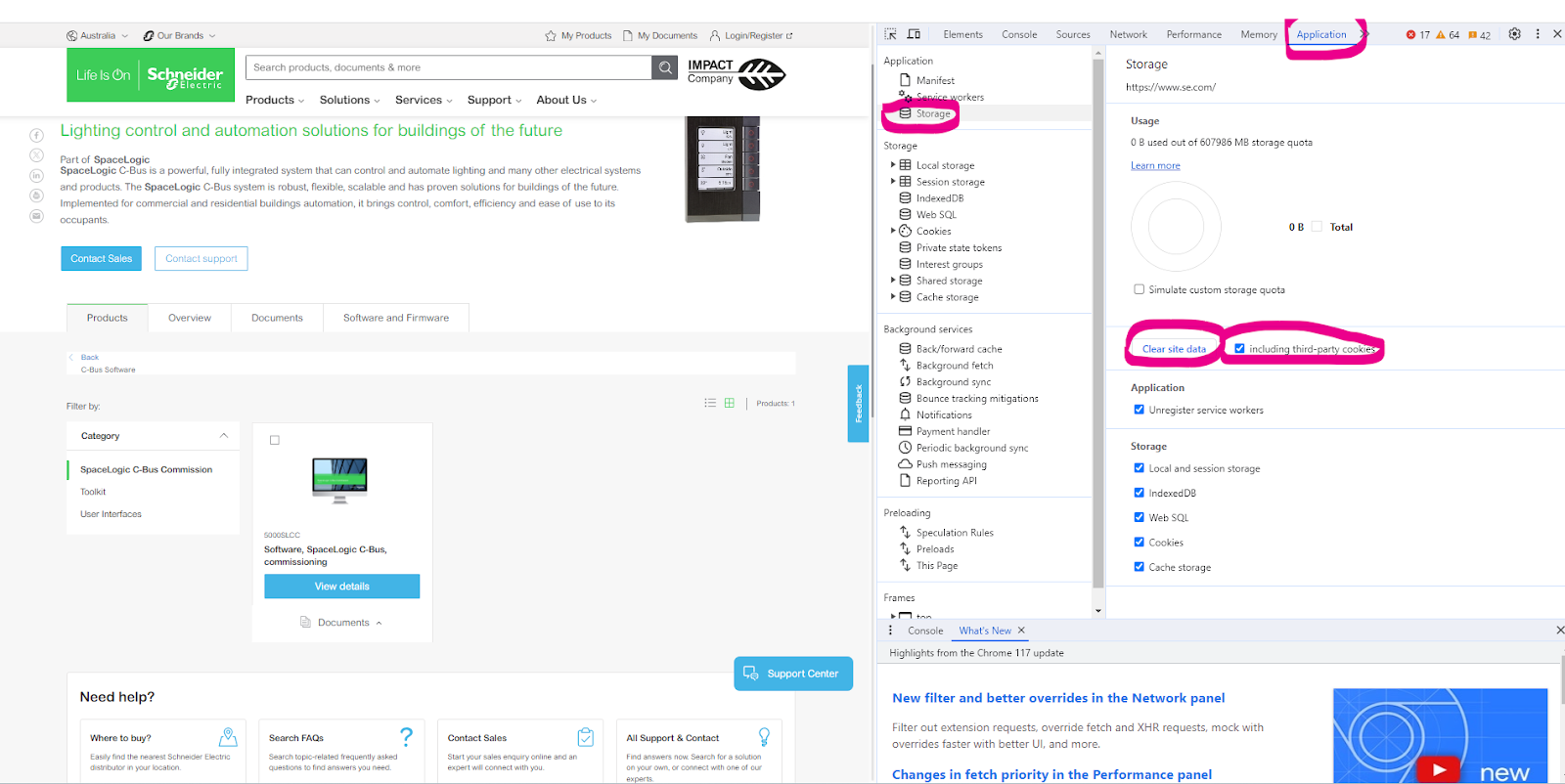
Select Application> Storage> tick including third-party cookies then hit > Clear site data
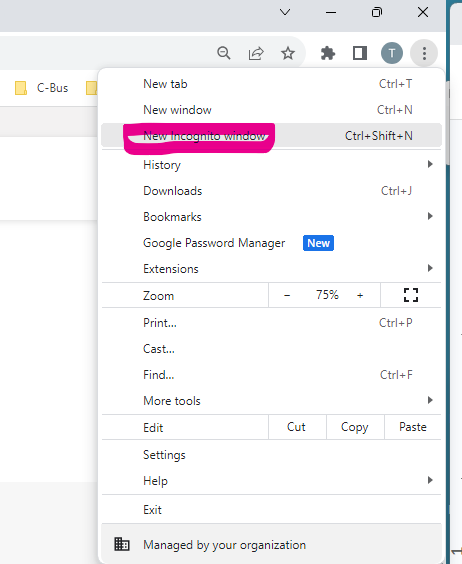
Another option is to run New Incognito window
What is the outer dimensions of the CAT5E 2D4P5IPV3B data cable?
Hide ShowSome of the key features are:
- Product standard certification: UL File E 215065
- Application: Horizontal wiring in LAN
- Complaint to RoHS standard: Yes
- Average thickness: 0.18 mm
- Minimum point thickness: 0.15 mm
- Insulation diameter: 0.87 mm
- Rip cord
- Bend radius: 50 mm
VIDEO - How to Test Interconnection of 755RFB2 Base with 755PSMA4 Smoke Alarm?
Hide Show►Learn More: https://www.clipsal.com
How to Enable +/- Speeds Around Preset Speeds on ATV320 Drive
Hide ShowIt is possible to set preset speeds on the ATV320 drive and also allow for manual speed adjustments above and below those presets. Please refer to the steps below.
- Set desired preset speeds in [PRESET SPEEDS] menu as shown.
RDY -> CONF -> FULL -> LAC -> Epr (Expert)
RDY-> CONF -> FULL -> Fun [Application Function] -> PSS - [Preset Speeds]
- Set up desired values for speed around reference in [SPEED AROUND REFERENCE] menu.
RDY -> CONF -> FULL -> Fun [Application Function] -> SrE (menu shown below)
Example:
Setting Access level to Expert access.
Assigning Digital Inputs 2 and 3 to control preset speeds (enabling up to three preset speeds)
Preset Speeds 2, 3, and 4 configured to 14 Hz, 18 Hz, and 22 Hz respectively.
Setting Digital input 4 for increase in speed (+).
Setting Digital input 5 for decrease in speed (-).
A +/- speed variation limit of 13% has been applied, restricting any increase or decrease from the preset speed to a maximum of 13%.
Acceleration and deceleration time for changing speed set to 5s.
Is bonding required for the internal foil of the 2D4P6AIPV3R-BU?
Hide ShowWhat are other benefits of the new design of Cat6A U/UTP cable?
Hide Show- Smaller physical dimensions on cable external diameter compared to previous Clipsal Cat6A UTP cable, thus reduced space requirements for multiple cable runs.
- New Cat6A UTP cable weight is 28% lighter than previous product
- New Cat 6A UTP cable uses less raw material to manufacture, resulting in reduced consumption of materials and resources.
- Higher performance against heat rise in case of PoE (Power over Ethernet)
Why is there an internal foil on the new design of Cat6A cable, 2D4P6AIPV3R-BU?
Hide ShowHow is the new design of Cat6A U/UTP cable terminated?
Hide ShowVideo: How to enable or disable an ION Meter Web Page?
Hide ShowIssue
When trying to connect to an ION meter through a web browser, an error " Page can not be displayed" or "This site can't be reached", depending on which web browser, is displayed.
Product Line
ION 8650, 8600, 7650, 7550, 7600, 7500
PM8000
Environment
ION Meter Web Page
Cause
The ION Meter Web Page has been disabled.
Resolution
Enable the ION Meters Web Page functionality.
Note: For PM8000 meters, ION Setup V3.0.15140.02 or later must be used. The latest version of ION Setup can be obtained from FA212816.
1. Connect to the meter in Advanced Mode using ION Setup.
2. Select the Comm Modules folder and then the Ethernet module.
3. Under the Setup Registers Tab, select ETH1 Enable Webserver and change the value to 'Yes' to enable the Web server, or 'No' to disable it. (Refer to the screen shot below)
NOTE: the ETH1 Webserver Config Access will enable or disable the ability to make configuration changes from the ION Meter Web Page.
Note: For instructions on connecting to an ION Meter in Advanced Mode, please refer to ION Setup 3.0 User Guide. Latest ION Setup User Guide can be obtained by visiting following link:
https://www.schneider-electric.com/en/product-range-download/61461-ion-setup-3.0
Please note that if the device is communicating over a managed switch, you may need to use the IP address signed by the switch when trying to browse the meter webpage.
How to set a Static or Fixed IP, for 5500CN2 C-Bus Network Interface
Hide Show
Assuming that it's powered up and connected to the same network where your PC is connected to.
Assuming that you have installed Toolkit software where C-Bus Control System IP Utility is also installed.
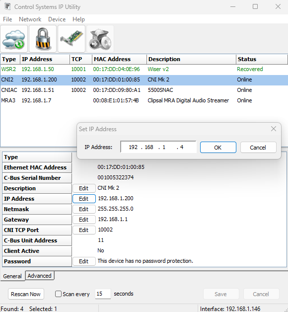
- From start menu run the C-Bus Control System IP Utility
- Select the Cloud Icon to scan for C-Bus network interface
- Select the C-Bus network interface you wish to specify the static IP address for
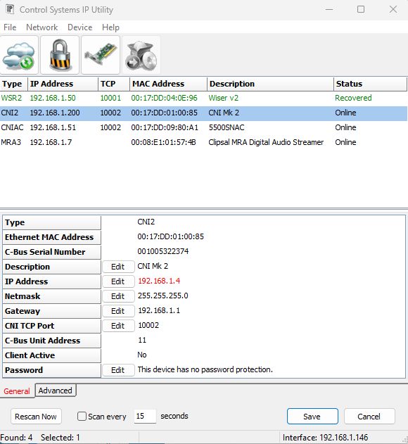
- Select the edit button and type the desired static IP address and click ok
- The new IP address will be showing in red
- Hit the save button will apply the change and the C-Bus network interface will reboot and shall now have the new IP address